

Sep 03, 2026
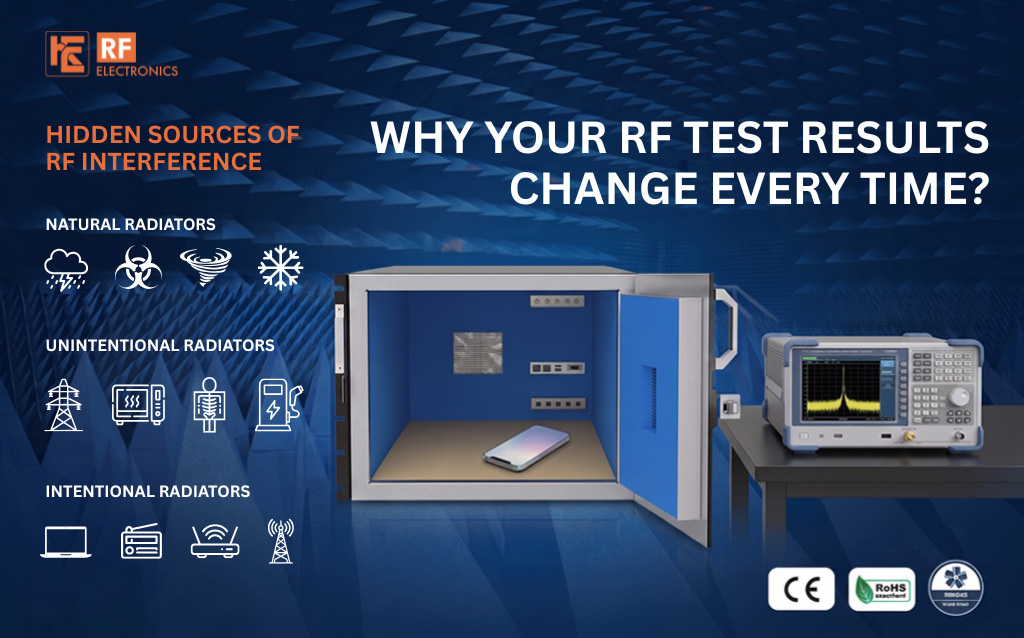
Wireless testing is supposed to produce repeatable results. Yet many RF engineers experience a frustrating situation: the same device, the same instrument, and the same test procedure can produce different results at different times.
One test passes. Another fails.
A measurement looks normal in the morning but changes later in the day.
The first assumption is often that something is wrong with the Device Under Test (DUT), test instrument, firmware, or measurement software. But in many cases, the real problem is much closer to the test setup: unwanted RF interference.
Modern laboratories are surrounded by wireless signals from Wi-Fi access points, Bluetooth devices, cellular networks, IoT equipment, computers, and other RF systems. Even when these signals are not visible to the engineer, they can influence sensitive wireless measurements.
This article looks at the hidden sources of RF interference that can affect test results and explains how engineers can create a more controlled and repeatable RF testing environment.
Why Do RF Test Results Change?
can all contribute to measurement variation.
The challenge is that some of these factors are not immediately obvious.
An engineer may repeat the same test and assume the conditions are identical, while the RF environment has actually changed.
One of the most common sources of unwanted RF interference is the wireless environment surrounding the test setup.
A typical laboratory may contain:
These devices can transmit signals close to the frequencies being measured.
For example, when testing a 2.4 GHz wireless product, nearby Wi-Fi and Bluetooth activity can potentially influence the test environment.
At higher frequencies, cellular and other wireless systems can also become relevant depending on the test location and frequency range.
The problem
The interference level may change throughout the day.
Someone entering the laboratory with a smartphone, a nearby access point changing channels, or another device starting a transmission can change the RF environment without anyone changing the test setup.
The solution
For sensitive RF measurements, use a controlled environment with appropriate RF shielding.
An RF Shield Box can isolate the DUT from external RF signals and help establish a more consistent testing environment.
Even if the laboratory appears quiet, RF energy can enter or escape a test enclosure through several paths.
Potential leakage points include:
A shield box may look physically closed while still providing insufficient isolation at the frequency of interest.
This is particularly important when testing devices that operate across a wide frequency range.
Why frequency matters
Shielding performance is not necessarily identical across all frequencies.
A design that performs well at one frequency may have different performance at another because of enclosure construction, seams, apertures, connectors, and other physical characteristics.
Therefore, engineers should evaluate the required RF isolation across the actual operating frequency range, rather than relying on a single isolation value.
RF cables are often overlooked when troubleshooting inconsistent measurements.
However, cables form an important part of the RF signal path.
A cable can introduce:
As frequency increases, cable performance becomes even more important.
For example, a cable suitable for a lower-frequency application may not provide the same performance at microwave frequencies.
What should engineers check?
Before selecting an RF cable, consider:
For compact RF test setups, conformable RF cables can also be useful where controlled routing and reliable high-frequency performance are required.
A simple rule
Don't treat the cable as just a connection between two instruments.
The cable is part of the measurement system.
A high-quality RF cable can still produce poor results if the connectors are damaged, incompatible, contaminated, or incorrectly installed.
Common issues include:
At RF and microwave frequencies, small mechanical issues can have a measurable effect on the signal path.
How to reduce the risk
Use compatible connectors and follow the appropriate installation and torque requirements for the connector type.
Where possible:
Consistency in the physical connection can be just as important as consistency in instrument settings.
The physical position of the Device Under Test can affect wireless measurements, particularly when antennas are involved.
Moving the DUT by even a small amount can change:
This can become especially important during OTA or antenna-related testing.
Imagine testing two identical devices.
If one device is positioned slightly differently from the other, the resulting measurement difference may be caused by the setup rather than the product.
Best practice
Create a defined DUT position and use a repeatable fixture whenever possible.
Document:
For production testing, automated positioning can further reduce operator-to-operator variation.
RF signals do not always travel directly from the transmitter to the receiver.
They can reflect from:
These reflections can interact with the desired signal and create changes in the measured response.
This is one reason why the physical design of the test environment matters.
A controlled RF test environment should be designed around the frequency range, DUT characteristics, measurement method, and required test accuracy.
Depending on the application, this may involve an RF Shield Box, absorber materials, a shielded enclosure, or a larger RF test chamber.
Sometimes the interference problem isn't an external signal at all.
The test setup itself may change.
For example:
Test A
Test B
The engineer may consider both tests identical, but electrically they may not be.
The solution: Standardize the setup
Create a documented test configuration covering:
The more repeatable the physical setup, the easier it becomes to identify genuine device performance changes.
Modern laboratories may test multiple wireless devices simultaneously.
For example, one bench could be testing:
If these systems operate in overlapping or nearby frequency ranges, they can complicate measurements.
This becomes especially challenging when testing multi-radio products.
A modern wireless device may itself contain several radios, making coexistence and interference considerations more important.
A controlled approach
Separate sensitive tests where appropriate and use RF shielding to isolate individual DUTs.
An RF Shield Test Box can provide a controlled environment around the DUT while allowing engineers to connect the required RF test equipment.
Sometimes the test environment is controlled but the measurement path has not been properly characterized.
Every component between the instrument and DUT can influence the measurement.
The signal path may include:

Each component can contribute loss or other RF effects.
If these effects are ignored, the engineer may interpret a system-level measurement as a DUT performance issue.
How to improve confidence
Engineers should understand the complete RF path and account for relevant losses and characteristics.
Depending on the measurement method, calibration and verification procedures can help establish confidence in the setup.
The objective is simple:
Know what your test system is contributing before deciding what your DUT is contributing.
Not all measurement variation comes from RF signals.
Environmental conditions can also affect RF equipment and the DUT.
Changes in:
may contribute to measurement differences depending on the equipment and application.
For long-duration testing or highly sensitive measurements, environmental conditions should be monitored and controlled according to the applicable test requirements.
An RF Shield Box provides a controlled enclosure around the Device Under Test.
Its primary purpose is to reduce unwanted RF interaction between the DUT and the surrounding environment.
A properly designed RF Shield Box can help:
Reduce external interference
External RF signals are attenuated before reaching the DUT.
Improve repeatability
Tests can be performed under more consistent RF conditions.
Reduce signal leakage
The DUT's transmitted signals can be contained within the controlled environment.
Support automated testing
RF Shield Boxes can be integrated into automated test systems for R&D and production applications.
Improve troubleshooting
When environmental interference is reduced, engineers can focus more directly on the actual behavior of the DUT.
When RF test results suddenly change, don't immediately assume the DUT has failed.
Work through the test environment systematically.
Step 1: Check the RF environment
Ask:
Step 2: Check the shielding
Inspect:
Step 3: Check the cables.
Verify:
Step 4: Check the DUT.
Confirm:
Step 5: Check the instruments
Verify:
Step 6: Repeat the test
Once the suspected issue has been corrected, repeat the measurement using the same documented configuration.
This systematic approach can help distinguish a genuine product issue from a test-environment problem.
The best way to reduce inconsistent results is to design the test environment for repeatability from the beginning.
A reliable setup typically considers:
1. RF isolation
Choose an appropriate shielding solution based on the frequency range and required isolation.
2. Signal path
Use suitable RF cables, connectors, adapters, and interfaces.
3. DUT positioning
Use repeatable fixtures and defined positioning.
4. Test equipment
Ensure measurement instruments are suitable for the application and properly maintained.
5. Documentation
Create standardized test procedures and configuration records.
6. Automation
Where testing volume is high, automate repetitive operations to reduce human variation.
RF Shield Boxes are useful across several stages of wireless product development.
R&D Testing
Engineers can isolate prototypes while investigating antenna, connectivity, and RF performance.
Validation
Controlled testing helps teams compare hardware and firmware changes under consistent conditions.
Pre-Compliance Testing
Shielded environments can help reduce unwanted external signals during preliminary evaluation.
Production Testing
RF Shield Boxes can support repeatable testing of manufactured devices and can be integrated with automated workflows.
Applications can include:
RF Electronics provides RF testing solutions designed for controlled wireless measurement environments.
Its portfolio includes RF Shield Boxes, RF Shield Test Boxes, RF test racks, RF coaxial cables, and related RF testing solutions for applications across telecommunications, aerospace, defense, research, IoT, and wireless product development.
For engineers dealing with inconsistent RF measurements, the goal should not simply be to repeat the same test more times.
The goal should be to understand and control the variables that can change the result.
That includes the RF environment, shielding, signal path, cables, connectors, DUT positioning, instrumentation, and test procedure.
When RF test results change from one measurement to another, the problem is not always the device.
External RF interference, insufficient isolation, cable losses, connector problems, DUT positioning, reflections, environmental changes, and inconsistent test configurations can all influence wireless measurements.
The solution is a controlled and repeatable RF test environment.
By identifying hidden sources of RF interference and systematically controlling the complete test setup, engineers can improve measurement confidence, reduce false failures, minimize retesting, and accelerate wireless product development.
For modern Wi-Fi, Bluetooth, 5G, IoT, and other wireless technologies, reliable RF testing starts with controlling the environment in which the test takes place.
1. Why are my RF test results inconsistent?
Inconsistent RF results can be caused by external interference, inadequate RF isolation, cable losses, connector problems, DUT positioning, reflections, instrument settings, or changes in the test environment.
2. How does RF interference affect wireless testing?
Unwanted RF signals can interact with the DUT or measurement system and affect parameters such as signal level, receiver sensitivity, throughput, packet performance, and other RF measurements.
3. Can Wi-Fi interference affect RF testing?
Yes. Nearby Wi-Fi access points and other wireless devices can introduce RF energy into a test environment, particularly when testing devices operating in overlapping frequency ranges.
4. How can an RF Shield Box improve test repeatability?
An RF Shield Box provides a more controlled RF environment by reducing unwanted external signals and limiting RF interaction between the DUT and its surroundings.
5. Can RF cables cause inaccurate test results?
Yes. RF cables can introduce insertion loss, reflections, impedance mismatch, and other effects that influence measurements. Cable selection should match the frequency and requirements of the test setup.
6. Why is DUT positioning important in RF testing?
Changes in DUT position or antenna orientation can alter coupling, reflections, and signal paths. Using a repeatable fixture and defined DUT position helps reduce measurement variation.
7. What is RF isolation?
RF isolation describes how effectively a test environment or enclosure prevents RF signals from entering or leaving the controlled area. It is typically evaluated across a specified frequency range.
8. Do RF Shield Boxes support automated testing?
Yes. RF Shield Boxes can be designed or configured for integration with automated RF test systems, programmable instruments, and production test workflows.
9. How can I troubleshoot RF interference in a test lab?
Start by checking nearby RF sources, shielding, cables, connectors, DUT positioning, instruments, and the complete signal path. Standardizing the test setup can help identify the source of variation.
10. What should I consider when choosing an RF Shield Box?
Important considerations include frequency range, required RF isolation, DUT size, connector and I/O requirements, cable interfaces, test method, automation requirements, and the intended R&D or production application.


 Item added to cart



.png)